![]() Steps and tips in Simulation tool, Affirma Analog Simulation Environment
Steps and tips in Simulation tool, Affirma Analog Simulation Environment
There are lots of simulation tools in cadence software kit. Here, I only introduce one of them called 'Spectre'. Before we start the following Q&As, please have a complete schematic.
![]() Where is the official tutorial?
Where is the official tutorial?
![]() Sorry, they only provide "User Guide", which is located at "/usr/apps/eda/cadence/doc/anasimhelp/chap2.html#about".
And Reference at "/usr/apps/eda/cadence/doc/spectreref/spectrerefTOC.html#firstpage"
Sorry, they only provide "User Guide", which is located at "/usr/apps/eda/cadence/doc/anasimhelp/chap2.html#about".
And Reference at "/usr/apps/eda/cadence/doc/spectreref/spectrerefTOC.html#firstpage"
The content table of Affirma Analog Circuit Design Environment User Guide, Product Version 4.4.6 is at "/usr/apps/eda/cadence/doc/anasimhelp/anasimhelpTOC.html"
![]() How to simulate my design?
How to simulate my design?
![]() From the schematic window, click "Tools->Analog Environment", then
the "Affirma Analog Simulation Environment" will appear.
From the schematic window, click "Tools->Analog Environment", then
the "Affirma Analog Simulation Environment" will appear.
![]() What simulator I should choose?
What simulator I should choose?
![]() Here, I only introduce "Spectre". So please choose "Spectre"
when you are choosing the simulator.
Here, I only introduce "Spectre". So please choose "Spectre"
when you are choosing the simulator.
![]() What is Model Library Setup? Do I need to setup if I use default library?
What is Model Library Setup? Do I need to setup if I use default library?
![]() Model Library is used to define the MOS or other components in simulation.
Without giving the required model library, you cannot run the schematic. Because I
download the 0.18um process model file from MOSIS, here, I have to assign where
the model file is. Attention!! Before assigning the model file, you must assign
which simulator you want to use. Otherwise, you will get the wrong window. If
you use the model file from your instructor or from this site, just locate the
file here.
Model Library is used to define the MOS or other components in simulation.
Without giving the required model library, you cannot run the schematic. Because I
download the 0.18um process model file from MOSIS, here, I have to assign where
the model file is. Attention!! Before assigning the model file, you must assign
which simulator you want to use. Otherwise, you will get the wrong window. If
you use the model file from your instructor or from this site, just locate the
file here.
![]()
The model file for MOS is log018.scs. If there is some other components, like resistor, in your design, you might have to include ResModel.scs. Besides, there are lots of configuration in the model file. Take log018.scs for example, section 'tt' is for normal MOS working under 1.8v power supply. If you want to try different MOS like fast mode, slow mode, or MOS under 3v power supply, you need to assign different section. After the directory is assigned, click on 'Add' and then 'OK' to leave this window. If you have some other components that aren't defined in log018.scs, be sure to add the required file again. (It's because log018.scs only defines the property of transistor, if you want the definition of resistor, you need to include some other files)
For further information about the configuration in model file, please using the word editor to open the file for detail.
![]() Where can I assign the value for input port?
Where can I assign the value for input port?
![]() Click on Setup->Stimuli, then a window will be pop-up. First, check out how
many inputs that you have to make sure and see if the number of inputs here is
the same as that in schematics. Second, click on 'Global Sources' and see if the
power supply is present for assignment.
Click on Setup->Stimuli, then a window will be pop-up. First, check out how
many inputs that you have to make sure and see if the number of inputs here is
the same as that in schematics. Second, click on 'Global Sources' and see if the
power supply is present for assignment.


Do you see 'OFF' here? For every assignment, you need to activate this stimuli such that Spectre will take it into account. The way to activate is to check the box, 'Enable'. After filling in the required value, be sure to click on 'Change' to make it work.
![]() About the PWL, something you need to know....
About the PWL, something you need to know....
There is one thing you need to take care of when you assign the signal with PWL (Piecewise Linear) type. Remember to assign the length of sequence; otherwise, the default value is "2", which means only the first and second pairs will be considered. As for the period of signal and Delay time, you could just leave them blank if you don't need it.

![]() Where can I assign the run time for this design?
Where can I assign the run time for this design?
![]() Click on Analyses->Choose, then assign either the 'tran' (transient
analysis), 'dc' analysis, etc. For transient analysis, you need to provide the
Stop Time.
Click on Analyses->Choose, then assign either the 'tran' (transient
analysis), 'dc' analysis, etc. For transient analysis, you need to provide the
Stop Time.


![]() How to see the output waveform?
How to see the output waveform?
![]() Yeah, after these configuration, it should be the time to start our simulation.
However, before starting it, we can assign which net we want to observe and get
the waveform just after the simulation. (Actually, you could assign it after the
simulation because this simulator will store all the information.). Here we go,
Yeah, after these configuration, it should be the time to start our simulation.
However, before starting it, we can assign which net we want to observe and get
the waveform just after the simulation. (Actually, you could assign it after the
simulation because this simulator will store all the information.). Here we go,
1. Output->To be plotted->Select on Schematic
2. Select the signal you want to see. If you want to check the voltage, you should click on the wire, and then the wire will change its color; if you want to check the current, you should click on the node of the element. (How do you know if you already precisely activate it? Once you select the node, there should be a circle present. If you don't see this circle, it means you don't select this circle.) This color will be the same as it is on the final waveform.
![]() How to de-activate the signal?
How to de-activate the signal?
Yeah, it is very important, isn't it? If you make an mistake, you could click on that net again, then this signal will be de-activated. Very easy, right?

After assigning these wire, if you have already finished the simulation, you should then click on Results->Plot outputs-> Transient (Because we do Transient Analysis) , then the output window will appear.
![]() Can I use variables?
Can I use variables?
![]() Sure,
I think all of you will like to sweep the size of the transistors to get the
best size, and in some other tools, it seems that we don't have this function or
may need a little bit difficult steps to finish it. But here, Cadence provides a
very easy and efficient way to do it. Actually,
there are two kinds of methods to setup your variable; please check the
followings.
Sure,
I think all of you will like to sweep the size of the transistors to get the
best size, and in some other tools, it seems that we don't have this function or
may need a little bit difficult steps to finish it. But here, Cadence provides a
very easy and efficient way to do it. Actually,
there are two kinds of methods to setup your variable; please check the
followings.
1. For the testing of one block:
First, click on one component, let's say NMOS. Press the middle bottom of the mouse and select 'Properties..', or you could only press 'q'. In any one of the column, key in any name you like. Then you could do simulation.
The final graph will look like this:

When you are doing simulation, remember to change simulator
to 'Spectre' first, otherwise, the variables you assign will disappear when you
change the simulator. Then choose 'Variable->Copy from cellview', then the
variables you assigned in the schematic will appear in the field, 'Design
Variables'. Finally, click on 'Variable->Edit' then you can edit the value of
variable. What's more, you could assign the value of a variable equal to another
variable, like a=b*4.2. The simulator will automatically arrange the order of
this two variables to make 'b' in front of 'a'. (Here, I assume these two
variables both extract from the schematic). Besides, you could create a
variable. Like 'b' is the variable you create and 'a' is from the schematic, or
you can define another new variable, such as ratio, and let b=a*ratio, and then
assign the value of ratio.
If you have lots of variables and don't know where he is in the design, you can click on Variables->find, then the symbol with this variable will be selected.
Attention, the variable I mention here is global variable, which is the same meaning when you are using a global variable in a C code. (ps. you have better not use a number as the beginning of the variable; the simulator can still read it but may result in some unknown error.)

2. For the hierarchy of system
It's very common to use a symbol very often, but sometimes
you may assign different value for the same part in a symbol. Let's say, we want
to make a ring oscillator, which has five inverters in it. If we have following
situation, the width of p transistor is always 4.2 times of the width of n
transistor; the size of the transistors of the next inverter is always 2 times
larger of the former one. How could you deal with it? Setup lots of variables?
Not a good method, isn't it? Here, I will give you another option, using
pPar("variable") and iPar("variable"). These
two commands are hierarchy commands, which means you have to assign a value, a
global variable, or even another hierarchy command for it when you use this
symbol in another schematic. For the above question, we can solve it as
following:
width of N transistor: pPar("wn")
width of P transistor: pPar("wn")*4.2

when we call an inverter, there will be another column in the "Properties" window call 'wn'. For the first inverter, we can assign a global variable, for example, 'first_wn' for it (ps. you have better not use a number as the beginning of the variable; the simulator can still read it but may result in some unknown error.) And for the next inverter, you could assign the value as 'first_wn*2', and first_wn*4, ..., for the following inverters. Then when you simulate it, you only need to assign the value of first_wn.

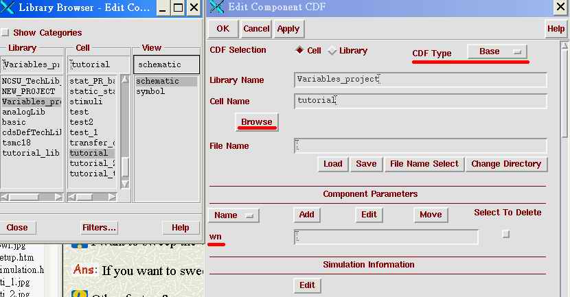
Actually, these parameters are called CDF parameters. Because it's a CDF parameter, you need to be very careful for that. If you want to change the name (add or get rid of any one of the parameter), you have better go to the CDF edit window to check if the parameter you just added/subtracted/modified has been valid. How to do it? First, go to the CIW window, click on 'tools->CDF->edit'. Then find out the name and library of the symbol, and change the CDF type to 'base'. If you find out there is a CDF parameter which shouldn't be here, click 'Select To Delete' to delete this parameter. Remember to activate this change when finish this job.
![]() I want to sweep the variable like what I did in Hspice, how can I do it?
I want to sweep the variable like what I did in Hspice, how can I do it?
![]() If you want to sweep
If you want to sweep
![]() Other feature?
Other feature?
![]() Hey, do you remember every time when you use Accusim to run your design, you
need to assign the output port first; otherwise, you might not see the
waveform. Here, for cadence user, you don't need to assign the port. Just go
ahead and run the design first, then choose what wire signal you would like to
see, and finally, click on 'Results->Plot Output'. The waveform will appear!
There is another way to see your waveform. If you want to check this signal just
for this time and don't want this signal to be plotted every time you click on
'Results->Plot Output', you could try 'Results->Direct Output' and the
waveform will be pop-up.
Hey, do you remember every time when you use Accusim to run your design, you
need to assign the output port first; otherwise, you might not see the
waveform. Here, for cadence user, you don't need to assign the port. Just go
ahead and run the design first, then choose what wire signal you would like to
see, and finally, click on 'Results->Plot Output'. The waveform will appear!
There is another way to see your waveform. If you want to check this signal just
for this time and don't want this signal to be plotted every time you click on
'Results->Plot Output', you could try 'Results->Direct Output' and the
waveform will be pop-up.
![]() What's Calculator? Could you tell me how to use it?
What's Calculator? Could you tell me how to use it?
![]()